
- #CODING LCD ARDUINO HOW TO#
- #CODING LCD ARDUINO CODE#
- #CODING LCD ARDUINO SIMULATOR#

You will need an updated I2C LCD library – LiquidCrystal_I2C-masterīefore displaying text on the LCD, you need to find the LCD I2C address.
#CODING LCD ARDUINO HOW TO#
To install the ESP8266 add-on in your Arduino IDE, read the following tutorial: How to Install the ESP8266 Board in Arduino IDE. In short, your backpack is based on PCF8574T and the address connections (A0-A1- A2) are not bridged with solder it will have the slave address 0x27.īefore proceeding with the project, you need to install the ESP8266 add-on in the Arduino IDE. If your module holds a PCF8574AT chip, then the default slave address will change to 0x3F. This i2c module are centered around PCF8574T (SO16 package of PCF8574 in DIP16 package) with a default slave address of 0x27. The PCF8574 is a silicon CMOS circuit provides general purpose remote I/O expansion (an 8-bit quasi-bidirectional) for most microcontroller families. this is a general purpose bidirectional 8 bit I/O port expander that uses the I2C protocol. Using the LCD backpack module, desired data can be displayed on the LCD through the I2C bus. Hitachi’s HD44780 based 16×2-character LCD are very cheap and widely available. On a “regular” LCD you need to add a potentiometer to the circuit to adjust the contrast. You just need to wire the SDA and SCL pins.Īdditionally, it comes with a built-in potentiometer you can use to adjust the contrast between the background and the characters on the LCD. The advantage of using an I2C LCD is that the wiring is really simple. Here's some useful info on getting that PCB made.For this tutorial we’ll be using a 16×2 I2C LCD display, but LCDs with other sizes should also work. The project has a "Download Gerber" button that will get you the files necessary to give to a printed circuit board (PCB) manufacturer to have a custom printed circuit board made. If you are so inclined, you can also make a circuit board to nicely connect your electronics to the Arduino. There's also a full-featured debugger where you can step through the program line-by-line and see what's going on! #CODING LCD ARDUINO CODE#
You can then edit the source code and try out changes right there. If you want to make any changes to the game, or explore what's going on, you can copy the virtual circuit using the "Duplicate Project" button. You can actually play the game right in your browser without ever having to put together any actual electronics ("Oh, now you tell me").

Here's the virtual circuit for the Arduino LCD game. I actually had the game fully working and tested before ever taking the Arduino out of the kit.
#CODING LCD ARDUINO SIMULATOR#
I developed this game entirely using the very cool (FREE!) online electronics simulator Tinkercad Circuits.

If you want to change the way the game works, or make a cool printed circuit board for this project that plugs directly onto the Arduino and replaces of all those messy wires, here's how to get started. Connect the other pin at the top of the button to pin 2 of the Arduino.Īt this point you have everything working, so what more is there to do? Connect one of the top two pins of the button to the black row at the top of the breadboard using a short hookup wire. Plug the pushbutton somewhere to the left of the LCD screen, straddling the channel running along the center of the breadboard (see picture above).
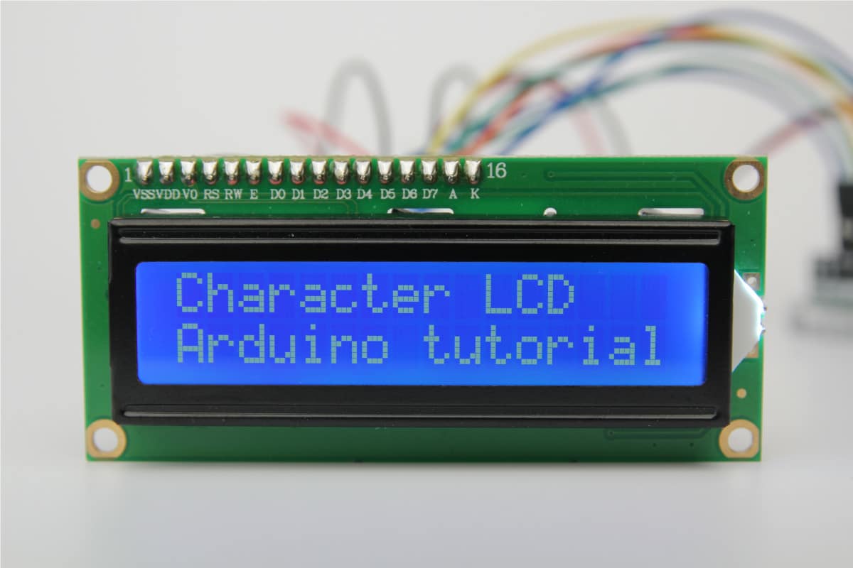
Connect V0 to Arduino pin 12 (or to black row at top of breadboard). Connect R/W to Arduino pin 10 (or to black row at top of breadboard). Use longer hookup wires to make the remainder of the connections: Similarly, connect VCC (pin 2) to the red row at the top with a short hookup wire.īend the wire leads of the 220 Ω resistor (red-red-brown colored bands) and connect it between LED+ and the red row at the top of the breadboard. Using short hookup wires, connect GND and LED- (pins 1 and 16) to the black row at the top. All of the electronic signals that power and control the LCD go through this header. Plug this into the breadboard as shown in the picture. LAST REVISION:, 07:46 AM This article was revised on 8 by Karl Sderby. The LCD (Liquid Crystal Display) module has a 16-pin male header on the underside. Liquid Crystal Displays (LCD) with Arduino Find out how to wire an LCD to an Arduino, and how to use the LiquidCrystal library through a set of useful examples. Use a long hookup wire to connect the GND signal to the far left of the black (or blue on some breadboards) row at the top of the breadboard. Use a long hookup wire to connect the 5V signal on the Arduino to the far left of the red row at the top of the breadboard. That will happen in a later step when it is time to program it and try the game out. The parts needed are shown in the picture above.


 0 kommentar(er)
